
|
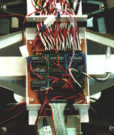
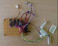
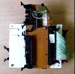
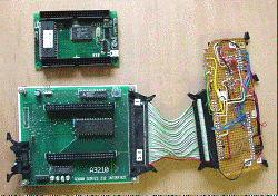
The 50-pin cable (right side of the board) comes from RS232 interface board. The 20-pin cable is connected to the robot. The 40-pin cable is connected to PC or Pocket computer. The cable that connects this board and the robot is about 3 m. |
|
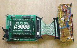
The board on the top of this controller is expanded. The 10-pin cable is connected to the connector at the left side of the RS232 interface board for serial communication. |
|
The Z80 CPU card is removed. |
|
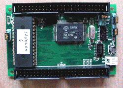
This is a close-up of the CPU card. The clock frequency of this card is 6MHz and equipped with 32Kbyte of ROM and RAM. The Z84C1106 has five sets of 8 bit I/O and four sets of counter/timer. |
|
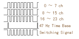
The waveform shown left is the signal that is output to the robot through the 20-pin cable. There are three lines for servo control signal. The signal for 8 servomotors is gathered in each of the line. When TTL IC is connected with long cable (over 30 cm), problem about reflection of signal and noise may be considered. But the frequency of these signals is low enough. So ICs are just connected in this controller. |
The circuit diagram can be downloaded for a reference. The diagram is not complete (because it is drawn for my memorandum) but I think this will help to understand what it is. (31 Kbyte GIF file)
